| Specifications | |||||||
|
|||||||

Say Goodbye to Knobs, Pots, and Hundreds of Different Timers!
Introducing the New Digital Programmable Timed Delay Relay (TDR)
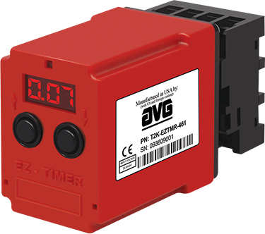
EZ Timer, all digital programmable timers offer flexible features at a great price. The large, bright red LED display has a 12 mm character display height. No knobs, only digital settings to 1% resolution, 1% absolute accuracy and 0.1% repeat accuracy, so operation is easy. Widest Time delay ranges from 0.01 sec to 999 hrs. Password protection/security is available to avoid tampering with the settings.
 Four programmable Timer modes
- T1 (Delay On Make or Timed On Delay)
- T2 (Single Shot)
- T3 (Delay On Break or Timed Off Delay)
- Cycle
Modes of Operation
T 1 : Delay On Make / Timed On Delay
This type of operation indicates that the timer delay (SP) begins as soon as the input power at operating voltage (V) is supplied. The Relay (R) output is energized only at the end of the time delay and then it remains energized as long as input power is supplied. The timer and the Relay output are Reset on loss of power.
T 2 : Single Shot Timer
Input Power (V) must be applied to the timer before and during timing. Being Positive edge-triggered, the Relay (R) output is energized upon momentary or maintained closure of the switch (S1). The energized Relay also triggers the time delay (SP). When the timer finishes timing, the Relay de-energizes.
T 3 : Delay On Break / Timed Off Delay
Input Power (V) must be applied to the timer before and during timing. When the switch (S1) is closed, the Relay (R) output is energized. The time delay begins when the switch is opened (Negative edge triggered) and the output remains energized during timing. The output is de-energized at the end of the time delay.
CYCLE : Cycle Timer
When input power is applied at startup, the Relay output is energized and the TON timer begins. At the end of the TON time, the output de-energizes and the TOF time begins. At the end of the TOF time, the output is re-energized and the cycle repeats as long as power is applied.
Multi-Function Timer
10 different timer modes, including delay on make, delay on break, single shot, cycle, interval, retriggerable single shot, trailing single shot, inverted single shot, inverted delay on break, and accumulative delay on make.


